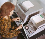
I am building a DIY system here mainly for fun, and to learn more about how the system works at a component level.
I am just looking at assembling the V1.50 Line Current card, and have a question.
From the schematic, and the board, it seems that there could be two ways to build the board, one, is the standard circuit, where the IRF530 switches the line current, and the other where a pair of transistors switch line current (looks a lot like a double current interface )
Is this correct, and if so, is the design intent that the board be fully populated with all components, and bridges select the operating mode?
Thanks
Sean
669089 Siemen G - T100S Online 24H (Online again)
299709 Antosh G - Creed 444 - Double Current R + D (0800 - 2100) Should be reachable
459724 NC
M1ECY hat geschrieben: ↑Sa 19. Dez 2020, 07:29
I am building a DIY system here mainly for fun, and to learn more about how the system works at a component level.
I am just looking at assembling the V1.50 Line Current card, and have a question.
From the schematic, and the board, it seems that there could be two ways to build the board, one, is the standard circuit, where the IRF530 switches the line current, and the other where a pair of transistors switch line current (looks a lot like a double current interface )
No, that's not possible.
The parts for the double current version would "disturb" the functions for the TW39 version and vice versa.
What is more, the components of both versions share partly the same positions on the board.
You would need to place numerus more jumpers and need to mount the parts with some cerativity.
Possible is the population of the board in that way, that one half is TW39 and the other half is double current.
Grüße,
Fred Sonnenrein, Braunschweig
i-Telex 952741 (Lo133), 8579924 (T100s), 781272 (T100), 792911 (T68d) oder 531072 (T.typ.72)
Bei besetzt oder gestört bitte 531002 versuchen.
Hi, I'm not an expert on this (yet), but I'll try to give some more insight afaik.
Find attached a schematic, which one I assume you're referring to, when writing version 1.50
The picture shows both independant channels on this card, where one is used with 4-wire interface and the other with 2-wires only.
For TW39 both, sender and receiver of the telex, are hooked up in serial to the card, so the 2-wire interface is the one that is mostly used to connect, for example, a T100 to the i-Telex card on connectors Ltg.a and b. This is the one side which uses the IRF530. It is also used on the newer TW39 cards, partially combined with a RS232 connection.
The other circuit uses separate lines for sender and receiver, two wires each with - and + polarity. By which machines this is used I have no idea, but I have seen this on the central side and also on some FSG i.e. LAG200 from Tekade.
So you can choose, which parts to install, depending on the function of the related circuit, either both channels as 2-wire or 4-wire or one channel of each. That's why some parts are crossed out on the attached schematic.
One difference might also be, that with 4-wire, the signal sent will not directly be seen on the receiver circuit as both are hooked up electrically independant.
Du hast keine ausreichende Berechtigung, um die Dateianhänge dieses Beitrags anzusehen.
Liebe Grüße
Beat Wyss - CH-4304 Giebenach BL
8582911 cull d (Lo3000) erreichbar 24/7 772786 kies d (T100) erreichbar 24/7
Those schematics helped me a lot recently when soldering my boards for i-Telex, and also for the understanding of the system, besides all the other documentation available. This really helps to understand what's going on.
And for somebody like me, who prefers hands-on stuff, it's just gr8, even when knowing and working with electronics for ages. I like it
Liebe Grüße
Beat Wyss - CH-4304 Giebenach BL
8582911 cull d (Lo3000) erreichbar 24/7 772786 kies d (T100) erreichbar 24/7
I have seen that the schematic at sourceforge was outdated.
It showed the correct concept, but not the correct parts.
Here is the correct one:
FsLinienstrom-Misch_BGT.sp.pdf
And in fact there are six different variants of board population:
a) TW39
b) single current (40 mA)
c) single current with additional relay for "self made" remote control unit, potential free contact
d) single current with additional relay for "self made" remote control unit, powered contact
e) double current
f) double current with additional relay for "weak" idle current
Du hast keine ausreichende Berechtigung, um die Dateianhänge dieses Beitrags anzusehen.
Grüße,
Fred Sonnenrein, Braunschweig
i-Telex 952741 (Lo133), 8579924 (T100s), 781272 (T100), 792911 (T68d) oder 531072 (T.typ.72)
Bei besetzt oder gestört bitte 531002 versuchen.